IMTS
Intelligent Metallic Test System (5U Shelf type)
 Key Customers
Mobile Communication Providers

Basic Informations
| Model | IMTS |
|---|---|
| Type | Intelligent Metallic Test System (5U Shelf type) |
| Interface | 50P Camp Connector_10port IEEE 802.3 Interface_RJ-45 |
| Applied Fields | Line Tester(RES/CAP/DCV/ACV/DCC/ACC) Frequency Measurement(Noise, tone_Tx/Rx) Monitoring and Call DC-48V(-43.5V ~ -54VDC) |
| Size | IMTS-M/S 584(W) X 254(H) X 280(D) MTAU 584(W) X 254(H) X 210(D) |
 LIST
LISTProduct Overview
Intelligent Metal Test System (IMTS) is a measurement device for measuring the characteristics of various lines, transmitting signals, and performing verification tests by connecting the main test points of the KT dedicated line section to identify the point of malfunction. IMTS is used to replace exiting Voice Frequency Test Unit (VFTU) system, as it became deteriorated, and developed to maintain compatibility with existing equipment, solid line cable, and Motion Preservation System (NeOSS). Also, Elementary Management System (EMS) is developed along with IMTS in order to improve lack of convenience on maintenance of existing equipment, by providing more graphical user interface.
Product Features
IMTS consist of IMTS-M/S (IMTS-M or IMTS-S) shelf and Metallic Test Access Unit (MTAU) shelf, and Local Access Jack Panel (LAJP), Local Access Test Terminal (LAT), and EMS are selectively tested and operated. IMTS-M/S: Responsible for the main control functions of IMTS and provide all the test functions.
 IMTS-M/S: Responsible for the main control functions of IMTS and provide all the test functions
- MTAU: Accommodates a dedicated line to subscribers and performs signal contact control
- LAJP: Enables various precision tests other than the measurement functions provided by the IMTS by monitoring the status of the connected subscriber line from the MTAU with an audible signal, or by connecting the line to the Jack Panel
- LAT: Enables full-function measurement and testing functions provided by IMTS to enable testers in base station to perform the same level of testing func-tions as those in customer centers
- EMS: Provides analysis on usage status or failure status of device, and device control function such as initializing setting of device or changing setting values
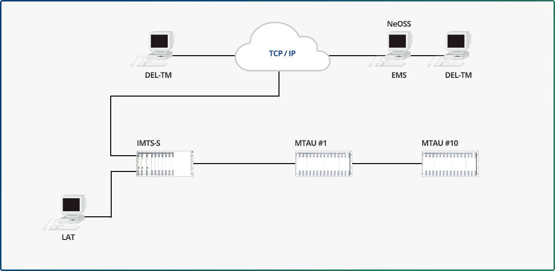
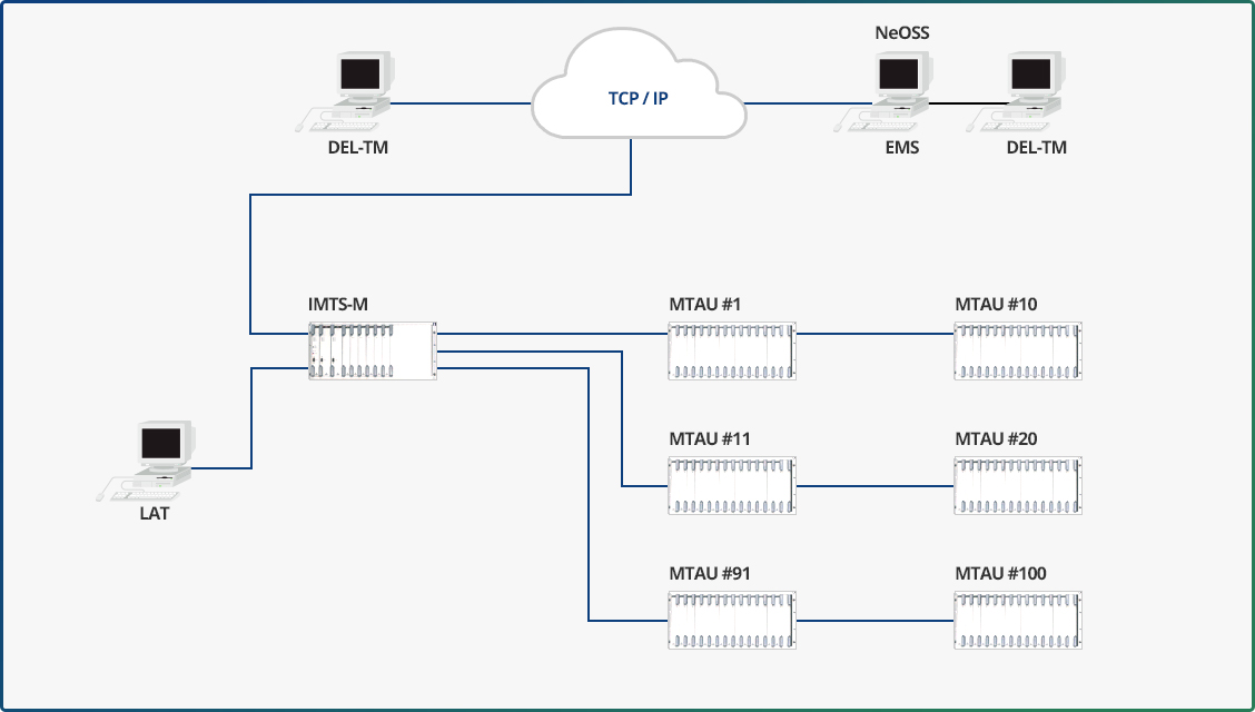
IMTS-M can accommodate up to 28,800 subscriber lines based on 2-wire type, and is eligible to accommodate up to 115,200 subscriber lines by expanding up to 4 units. It can also be replaced by IMTS-S, which has maximum capacity of 288 subscriber lines based on 2-wire type.
The configuration according to the line capacity of this device is shown in the following table.
- Capacity of lines for each IMTS model
| Classification | IMTS-S | IMTS-M | IMTS-M Extended |
|---|---|---|---|
| 2-Wire Type | 288 | 28,800 | 115,200 |
| 4-Wire Type | 144 | 14,400 | 57,600 |
| 6-Wire Type | 96 | 9,600 | 38,400 |
- Structures for each IMTS model
Configuration using IMTS-S
Configuration using IMTS-M
Specification
| Dimension (W x H x D) |
Rack | 700 x 2200 x 365 | |||
|---|---|---|---|---|---|
| IMTS-M/S | 584 x 254 x 280 | ||||
| MTAU | 584 x 254 x 210 | ||||
| LAJP | 584 x 43.7 x 266 | ||||
| Input Power | DC | -48V DC (-43.5V ~ -54V DC) | |||
| Power Consumption |
IMTS-M | 36.9W | |||
| IMTS-S | 17.4W | ||||
| MTAU | 4.5W | ||||
| LAJP | 3.9W | ||||
| Electrical Characteristic |
IMTS-M/S | Input Loss: Max 0.2dB Cross Talk : Min 70dB |
|||
| MTAU | Input Loss: Max 0.2dB Cross Talk : Min 70dB |
||||
| Environment Standard |
Operating Temperature & Humidity |
Standard Temperature | Standard Relative Humidity | ||
| 23℃ | 50% | ||||
| Operation Limit | Temp. Range | Absolute Humidity Range | |||
| Nominal Allowance | 15℃ ~ 28℃ | 40% ~ 70% | |||
| Short-Term Allowance | 2℃ ~ 50℃ | 20% ~ 80% | |||
| Short-term condition can be up to 72 consecutive hours or within 15 days from one full year |
|||||
| Storage Temperature & Humidity |
Standard Temperature | Standard Relative Humidity | |||
| -35℃ ~ 70℃ | 5% ~ 95% | ||||
| Vibration Standard | 5Hz ~ 100Hz 0.5g (Acceleration of Gravity) | ||||
| Noise Standard | Standard of 1.5m from equipment, Max 60 dBA | ||||
| Electromagnetic Interference |
Electromagnetic Conduction | Frequency Shift (MHz) |
Limit (dB㎶) | ||
| Peak | Average | ||||
| 0.15 ~ 0.5 | 79 | 66 | |||
| 0.5 ~ 30 | 73 | 60 | |||
| Electromagnetic Emission | Frequency Range (MHz) | Peak Limit (dB㎶) | |||
| 30 ~ 230 | 40 | ||||
| 230 ~ 1000 | 47 | ||||
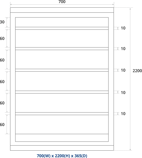
IMTS Structure
As show in Figure 3, the IMTS device can be installed in a general open rack with size of 700 (W) x 2200 (H) x 365 (D). If a Power Distribution Panel (PDP) currently used in KT is installed on the upper rack, space for IMTS-M/S or 5 MTAU shelves is available.

- Springwave Co.,Ltd
- 2F, Daechang Building 10-3, Hwangsaeul-ro 258beon-gil, Bundang-gu, Seongnam-si, Gyeonggi-do, Korea 13595
- E-mail : support@springwave.co.kr
- Tel : +82-31-272-2112
- Fax : +82-31-263-6569